Spec takes the next step toward
the vision of true smart dust. The idea
is to combine communication, computation, and sensing into a single tiny
package.
UC Berkeley has produced several version of Smart-Dust prototypes.
Spec is the first to integrate RF communication.
As many of
you heard yesterday, the single chip mote is working. Thanks to a ton of help from Al Molnar, Ben
Cook, Mike Scott and Brett Warneke, the single chip mote vision is a
reality. The high level details are that
it measures approx 2mmx2.5mm, has an AVR-like RISC core on it, 3K of memory, 8
bit On-chip ADC, FSK radio transmitter, Paged memory system, communication
protocol accelerators, register windows, 32 Khz
oscillator, SPI programming interface, RS232 compatible UART, 4-bit input port,
4-bit output port, encrypted communication hardware support, memory-mapped
active messages, FLL based frequency synthesizer, Over-sampled communication synchronization,
…
The first
successful test of Spec -> COTS motes was performed yesterday with communication
at 902.4 MHz to the a Dust Inc. mote using a CC1000
radio from Chipcon.
Spec was able to communicate 40 + feet indoors (through walls) at 19200 Kbps with a frequency
separation of 180 Khz.
The C code
controlling radio configuration and data transmission was compiled and
downloaded into the chip over the SPI interface and executed. The chip only required five external
components, 1) 4 Mhz
oscillator (to be removed in future designs) 2) a 15 nH
inductor, 3) a 32 Khz crystal, 4) a power source, 5)
Antenna.
The 5 mm2
of silicon costs approximately $0.30 to manufacture in quantities. The inductor $.01, crystal $.15, and battery,
$.16, round out rest of the potential future node cost.
The future
is coming….
Jason
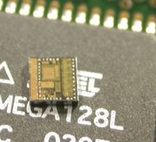
Here is a picture of Spec sitting on top of the previous generation of UC Berkeley Motes, the Mica node. The size reduction is staggering!!
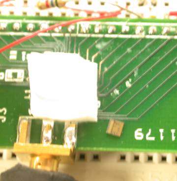
Here is a picture of the test setup used to test the first Spec. The chip under test is hiding under the white wax square. The chip was bonded directly to the PCB by Ben Cook. Al Molnar then encased the chip in wax. A second die is placed next to the wax block as a reference.
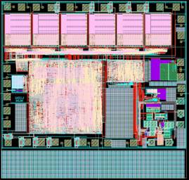
Here is the actual die layout: Can you see the features from the close-up above?
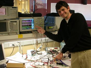
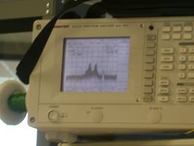
Here is a picture of the spectrum analyzer capturing the 19.200 Kbps FSK signal.
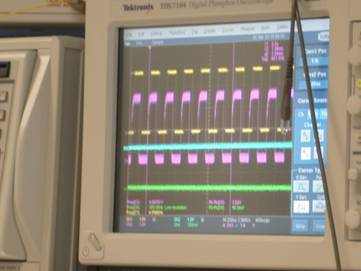
Here is a capture of the transmitted and received waveform. The pink waveform is the transmitted signal and the yellow wave from is the signal received by the CC1000 radio. (100% success !!!)
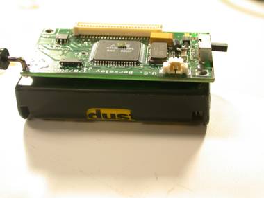
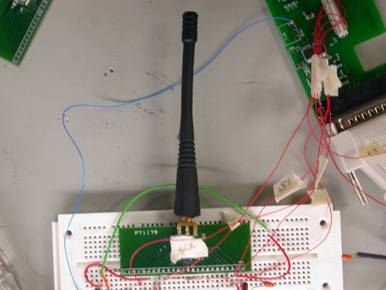
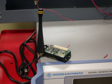
Here is the ENORMOUS node that was acting as the range test receiver: (a whopping 2x1.5). It was able to receive transmission from the spec at over 40 feet in the lab environment (through walls)
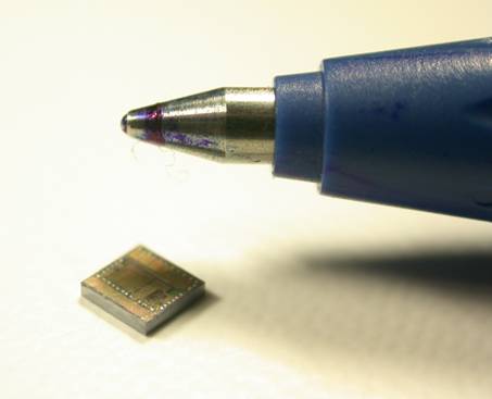
Another Spec Picture:
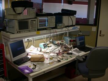
The work bench used to bring the mote alive. (What a mess)